APEX-delfino® Flow-Conditioner
Flow velocity maldistribution at the inlet of heat exchangers or other process equipment is a common bottleneck, frequently leading to heat exchanger failure or malfunction. However, this problem can be overcome with APEX Group’s patented innovation: the APEX-delfino® Flow-Conditioner.
Background: The Velocity Distribution Issue - Design vs Reality
Typically, during the thermal and hydraulic design of heat exchangers an important theoretical assumption is taken for granted: it is assumed that there is a uniform velocity distribution of the process stream at the inlet to the heat exchanger.
However, practice reveals that this theory is lacking; the velocity distribution at the inlet is not uniform. Instead, the velocity distribution is altered by a variety of factors, including: the pumping fan’s characteristics, the distance of the fan to the heat exchanger, the ductwork’s shape and dimensions.
This gap between theory and practice is not without its consequences. The non-uniform velocity distribution of the stream to the heat exchanger affects the heat transfer surface temperature, becoming either sub-cooled below, or super-heated above, the design value. On the one hand, sub-cooling can lead to corrosion problems in the “cold-end” of the Air Preheater; if heat transfer surfaces drop below the acid dew point of flue gas, then sulphuric acid can condense. On the other hand, super-heating may lead to mechanical failure due to excessive thermal expansion and/or accelerated creep rate of steel.
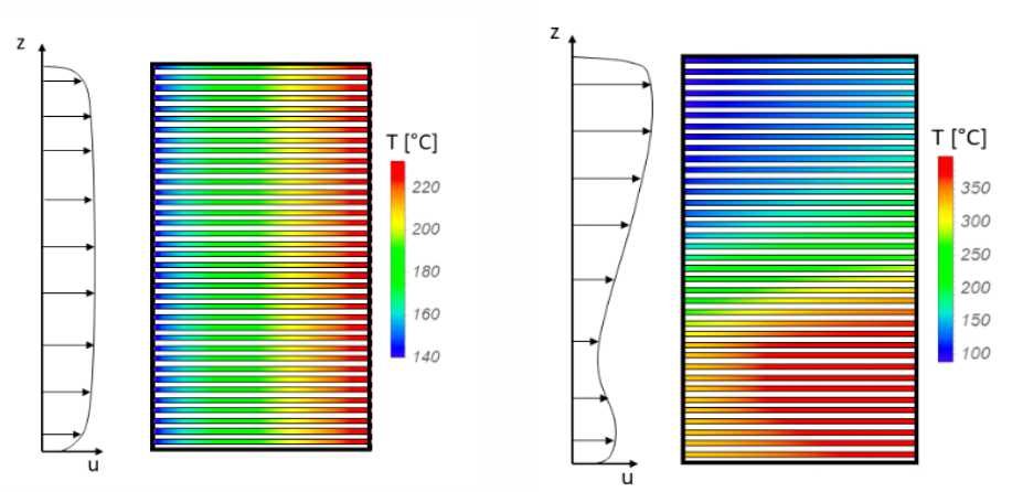
In figure 1, a comparison of the heat transfer surface temperature distribution at the flue gas outlet face of the Air Preheater is presented. The picture on the left presents the ideal design case, where the combustion air velocity distribution to the Air Preheater is uniform. The picture on the right presents the simulation of the actual field case, where the combustion air velocity distribution to the Air Preheater is non-uniform.
The comparison reveals the following data: in the field case the heat transfer surface minimum temperature is ~30% lower than the design minimum temperature. This results in condensation of the acid on the heat transfer surface, leading to corrosion.

Figure 1. Heat transfer surface temperature profiles at the flue gas outlet face of the Air Preheater; Design case (left), CFD simulation of the actual field case (right).
Extensive Laboratory Studies
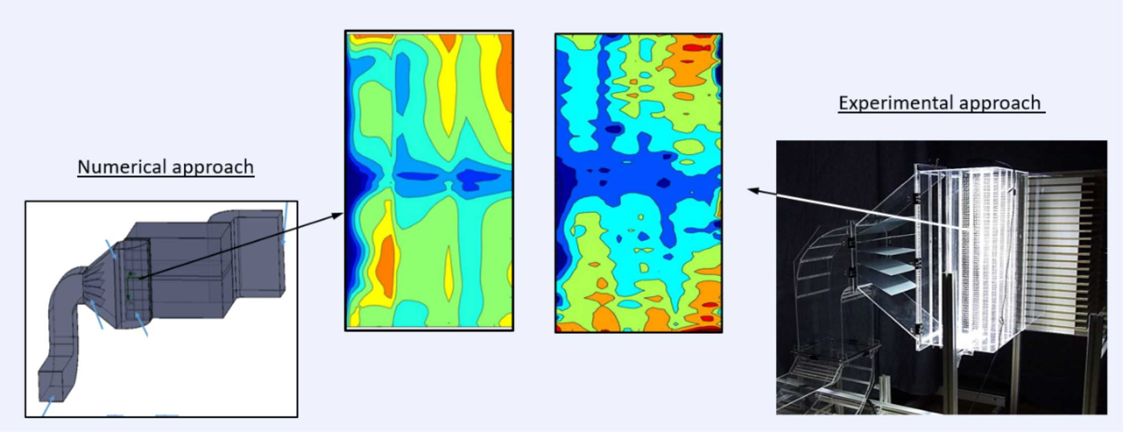
Engineers at APEX-Research have conducted extensive laboratory studies on the velocity distribution issue, employing cold flow modelling and laser optical measurement techniques (e.g., Laser Doppler Anemometry – LDA, and Particle Image Velocimetry – PIV). The results of these measurements were used to define the correct boundary conditions for the Computational Fluid Dynamics (CFD) simulations.
Figure 2 presents a comparison of the CFD simulation (on the left) with the optical measurement obtained from a scaled model of a gas-gas heat exchanger with a charging duct and forced draft fan (on the right). It is important to note the qualitative similarity of the results in both approaches.

Figure 2. Comparison of results from CFD (on the left) and optical measurements (on the right).
Uniform Velocity Distribution with APEX-delfino® Flow Conditioner
This research has led us to developing the APEX-delfino® Flow-Conditioner. This proprietary device is used to ensure the uniform velocity distribution of any gaseous stream to the process equipment. This helps to overcome the issues of designs based on incorrect theoretical assumptions, ensuring the expected performance of the process equipment downstream, such as Air Preheaters, DeNOx SCR Catalysts, Fired Heater’s manifolds to burners, etc.

Comparison Using CFD (Computational Fluid Dynamics)
In figure 3, a comparison is presented between a CFD simulation of an actual field case (on the left) and a simulation in which APEX-delfino® Technology is utilized (on the right).
In the field case – due to the non-uniform velocity distribution of the combustion air stream to the Air Preheater – the heat transfer elements have been locally sub-cooled and thus suffer from corrosion due to the condensation of acid in the flue gas.
In the simulation where an APEX-delfino® Flow-Conditioner is installed, along with other modifications such as optimization of the shape and size of the charging duct, the velocity distribution’s uniformity has been improved. This leads to no sub-cooling of the heat transfer surface across the complete inlet face of the Air Preheater.

Disclaimer: Perforated Plate versus APEX-delfino® Flow-Conditioner
Perforated plates have a limited thickness, which means that ‘swirls’ (i.e., spatial and temporal velocity fluctuations) in the stream’s flow field cannot be avoided. This negatively affects the thermal and hydraulic performance of the heat exchanger.
Yet, during the typical design process of perforated plates, the actual velocity profile of the flow field is neglected. Instead, perforated plates are designed with an assumption of a uniform resistance across the complete flow field. This approach leads to the creation of products which cause a much higher than necessary pressure drop to solve the velocity distribution issue.
The APEX-delfino® Flow-Conditioner, however, is tailor-designed to the velocity profile of specific flow fields. APEX Group ensures that the variable resistance across the flow field is precisely matched by its perforated plates. The construction of this product ensures a straightening effect and thus the elimination of ‘swirls’.
Overall, the overall hydraulic performance of the APEX-delfino® Flow-Conditioner outperforms conventional perforated plate concepts. This is because it ensures a uniform velocity distribution profile to the downstream equipment while ensuring a minimum pressure drop.
