APEX-Research B.V. set up a scaled-down transparent model of our plate-type heat exchanger to analyse and optimize the fluid mechanical properties, such as turbulence and pressure drop of our units. The transparent multi-channel facility allows the analysis of one fluid stream with Reynolds numbers ranging from 1.000 to 20.000, covering the laminar, the transitional as well as the turbulent flow regime.
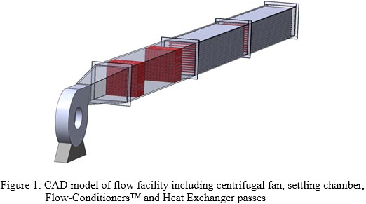
The CAD model is shown in figure 1. A centrifugal fan is activating the flow. The flow enters a diffuser and the following settling chamber. The settling chamber consists of two APEX-delfino® Flow-Conditioners™ to make the flow uniformly distributed in the entire cross section upstream of the heat exchanger model. The flow with a certain flow distribution enters the first pass and then the second pass of the heat exchanger model. The length of the channels equals 75 times the equivalent diameter of the channels, guaranteeing a fully developed flow state inside the channels of the heat exchanger model. Inlet and outlet geometries might be exchanged, allowing the study of the influence of inlet and outlet geometries.
The entire experimental set-up consists of transparent Plexiglas, allowing optical access for state-of-the-art laser optical measurement techniques, such as Laser Doppler Anemometry and Particle Image Velocimetry. Furthermore, the set-up is equipped with wall pressure sensors for measuring the pressure drop in different sections and channels.
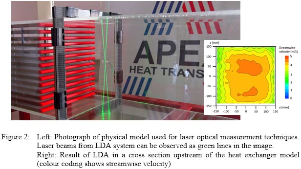
Laser Doppler Anemometry is a non-intrusive velocity measurement technique. Two laser beams are crossing in an intersection point, the so called measurement volume, see figure 2. The size of the measurement volume depends on the focal length (working distance) of the LDA system, but is usually in the range of 60 x 60 x 100 μm, allowing a high spatial resolution. To obtain a spatial velocity information, the laser system is traversed in the desired cross section. Figure 2 on the right shows the velocity distribution 125 mm upstream of the first pass.
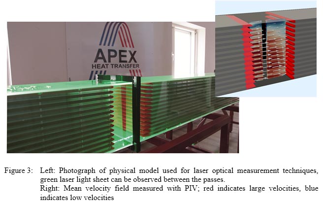
In contrast to the pointwise measurement technique LDA, Particle Image Velocimetry (PIV) is a planar measurement technique. PIV allows the instantaneous capturing of the flow field in a cross section and thus allows the analysis of coherent vortical structures and their influence on the flow behaviour. For that purpose, a pulsed laser equipped with a cylindrical lens generates a laser light sheet in the plane of interest. Scattered light of particles passing the laser light sheet are recorded by a 4 Mpixel CCD camera at two different time steps. The displacement of the particles can then be analysed by a cross correlation algorithm to calculate the velocity field in terms of velocity vectors.
Pressure sensors in the side walls of the ducts and in the side walls of each single channel of the heat exchanger model allow a description of the heat exchanger in terms of pressure drop. Minor losses can be distinguished from major losses and by that an optimization can be performed to reduce parasite pressure drop – any pressure drop that does not contribute to heat transfer.
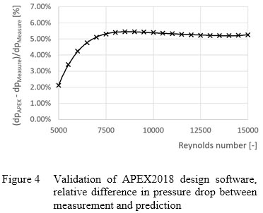
Furthermore, the pressure drop measurements are used to validate APEX2018 design software for our plate-type heat exchangers. A comparison between measurement results and predicted values from the design software is shown in figure 4. In the main application range between Re=5.000 and Re=10.000, the difference between prediction and measurement is below 5%. That accuracy allows an optimum design for our customers.
The transparent flow facility with the above-described measurement equipment allows an overall fluid-mechanical description of the flow inside the plate-type heat exchanger as well as the identification of influences on the overall performance of the heat exchanger (such as geometrical changes or a change of the inlet flow conditions).
Furthermore, the experimental set-up allows the validation of our proprietary design software APEX2018.